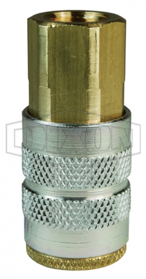
Image
pneumatic fittings display industrial dqc df series quick coupler set
Image
df series manual industrial coupler female threads
Image
Image

PND-DQCKIT1 - 1/4" Industrial DF-Series Quick Coupler Set - Retail Packaged

PND-DQCKIT1
Dixon Distributor? 

Log in to view pricing, inventory, place orders & much more. If you want to create an account, please click the button to begin the registration process.

Attributes

Weight
0.6 lb
Break Quantity
6
Mandatory Package/Box Quantity
6
Material
Brass
Steel
Maximum OD
Coupler - 0.93" (Coupler - 23.5mm, Female Plug - 20.1mm, Male Plug - 16.5mm)
Female Plug - 0.79" (Coupler - 23.5mm, Female Plug - 20.1mm, Male Plug - 16.5mm)
Male Plug - 0.65" (Coupler - 23.5mm, Female Plug - 20.1mm, Male Plug - 16.5mm)
Thread
NPTF
Body Size
1/4"
Temperature Range
-40°F to 250°F (-40°C to 121°C)
Thread Size
1/4"
Length
Coupler - 2.07" (Coupler - 52.6mm, Female Plug - 42.2mm, Male Plug - 42.9mm)
Female Plug - 1.66" (Coupler - 52.6mm, Female Plug - 42.2mm, Male Plug - 42.9mm)
Male Plug - 1.69" (Coupler - 52.6mm, Female Plug - 42.2mm, Male Plug - 42.9mm)
Hex
Coupler - 3/4"
Female Plug - 11/16"
Male Plug - 9/16"

Details

Compatibility & Interchange Data

  • Foster 3, 4, 5 and 6 Series
  • Parker 30 - Series Automatic Interchange & Parker 20-Series Manual Interchange
  • Hansen 3000, 4000, 5000 and 6000 & Hansen 1000, 400 and 500

Construction

  • Machined components are manufactured using solid bar stock.
  • Stainless steel balls, retaining rings and springs maximize corrosion resistance and extend service life.
  • Nitrile (Nitrile Rubber) seals are standard
  • Steel componentry is plated using ROHS Compliant Trivalent Chrome.
  • Steel sleeve and steel tubular valve

Description

(Case Qty 6 Required)

How It Works

  • To disconnect, begin by holding the hose on the nipple side with three of your fingers, leaving your thumb and index finger free.
  • Grab the sleeve with your thumb and index finger and begin to pull the sleeve towards the palm of your hand.
  • After pulling the sleeve, the nipple will move out of the coupler slightly.
  • Continue to hold the hose and coupler sleeve until all air is fully exhausted.
  • After the line is fully exhausted, you are able to safely separate the nipple from the coupler.

Includes

2FF2-B, D2F2, D2M2 (3)

Safety Notes

It is important to be safe when installing quick disconnect couplings into a pneumatic circuit. Never install a pneumatic coupling directly into an air tool, use a piece of hose that is at least 18" long, between the tool and the coupling, to prevent damage to the coupling. To protect the operator, safety devices, such as a safety check valve and safety cable should be installed in case there is a hose or coupling failure.

Specifications

  • Coupler - Rated pressure for connected Brass Coupler & Brass Plug: 300 PSI (20 bar) Maximum Working and 8,500 PSI (586 bar) Burst
  • Coupler - Rated pressure for connected Brass Coupler & Steel Plug: 500 PSI (35 bar) Maximum Working and 9,000 PSI (620 bar) Burst
  • Coupler - Rated pressure when connected with Brass F-Series Manual Couplers: 500 PSI (35 bar) Maximum Working and 9,000 PSI (620 bar) Burst
  • Coupler and Male Plug - Rated pressure when connected with Steel F-Series Manual Couplers: 500 PSI (35 bar) Maximum Working and 6,500 PSI (448 bar) Burst
  • Male Plug - Rated pressure when connected with Brass F-Series Manual Couplers: 500 PSI (35 bar) Maximum Working and 11,500 PSI (790 bar) Burst
  • Female/Male Plug - Rated pressure when connected with Brass D-Series Automatic Couplers: 500 PSI (35 bar) Maximum Working and 16,000 PSI (1,100 bar) Burst

Resources

    Request a Quote

    Need help selecting the correct components?